The BYOD 'BTTF' Time Machine:
Time Circuts & Internal Components
Last updated: January 29, 2004 3:15 PM (CST)


How To Build Your Own Darn
'BTTF' Time Machine.
==========
The Time Circuts

And Internal Components


Standard Liability Disclaimer: Although I have used these instructions in making my own props,
I accept NO RESPONSIBILITY if you ruin your own components or other parts
using these instructions. These techniques work for me, they might not work for you.
These instructions are worth exactly what you paid for them.


I hope you invested in that T1 internet connection because this page will give your 56k connection a workout. ^_^

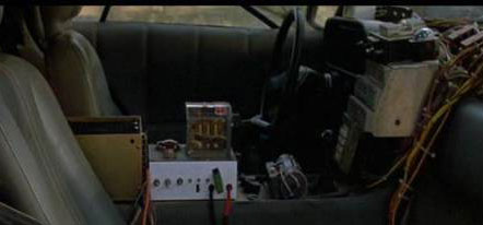
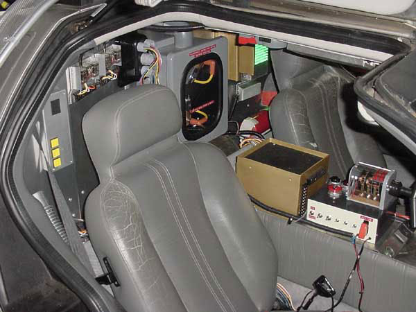
Mostly this is just the photos for now, shared by GWII. I'll give further info when I get to it...
Also note: All descriptions in this section that are in italics are direct quotes from GWII.
Any other text, descriptions and idiocy is courtesy of myself. ^_^


Most of the component photos in the car's interior are broken down by sections. They are...

The Driver's Side Center Console and Dash featuring the Time Circuts, TFD Switch Console and Overhead Switch Array.
The Driver's side Center Dash featuring the Time Circuts and Plutonium Gauges.
The Driver's Side Rear Bulkhead which features the Status Indicator Display, Flux Capacitor and overhead Switch Array.
The Passenger's side Rear Bulkhead featuring the Fuel System Regulator, Drive Relays, Wiring Bus, Flux Capacitor,
Secondary Power Supply and last, but not least, the TFDS switch console!

Having said that, I'm breaking them down by individual items. ^_^


Part 1: The Time Circuts: Driver's Side Center Console and Dash

Featuring the Time Circuts, TFD Switch Console and Overhead Switch Array.


Probably the easiest part to make from this whole involved project, is the actual switch and console that activates the time circuts.

The final product. Photo by GWII, (c)2003

There are several smaller components aside from the main switch unit kitself. The big red mushroom switch is...
a... big, red, mushroom switch. Sorry, it doesn't get any easier than that. ^_^

Um, well, it's a big, red, mushroom switch. What did you expect?

The Mushroom switches can be readily found on eBay, or possibly even at your local hardware store.
There is a black label on the switch that reads 'Reset.'

Approximate Price: Less than $15.00


The black and tan metal box is a project box from Radio Shack.
The size is appx. 8 x 6 x 3 inches. Model Number 270-274. The current colors may be black/tan or
Black/grey. Obviously Black/tan (or cream) is the correct color.

Approximate Price: $15.00


The thing on the side of the box that looks like a red switch cover is in fact...
a red Switch cover! Boy, the amazing secrets just keep coming, don't they?!?

The switch cover is typically used in airplanes and boats, so keywords like Nautical Switch Cover couldn't hurt.

Got an update from Jeremy...

Also, something you may want to address in regards to the time circuit switch is that the
red switch cover on Gary's replica
(and most being made) is actually green in the movie. I also was able to
find some screen accurate pilot lights. They are made by Dialco, NY and are surplus. I am
told that these are in rare supply but if someone runs across them they'll know what to look for.
The company name is stamped on the bottom of the sockets.


Approximate Price: $1.00 to $15.00


And as you have noticed, there's several switches on the side of the box.
Three of them appear to be metal, SPST (Single pole, single throw) switches. What that means is the switch is
either on or off, and there are only 2 positions the switch can be in, up or down. The switch under the red
switch cover is likely the same type of switch.

Approximate Price: $1.00 to $5.00


The three smaller switches I'm not sure of the designation. They appear to be a momentary contact switch
with a neutral (off) position. If you move the switch, it will return to the off position when released.
Perhaps someone with a little more information will shed some light on these switches.

Approximate Price: Unknown


Okay, onto the meat of the meal...

First, to make the Time Circut Control (TCC) activation switch you'll need a rotory drum switch.

Gary said...

The switch is nothing more than a Dayton 2X442 Drum Switch (you can get them from Grainger.com).
The cover is removed and replaced with a 4"x9 3/4", 1/8" thick acrylic cover bent to shape with a
heat gun. The Label is a custom made one printed to chrome adhesive vinyl since the original label
is no longer in production on Dayton Drum Switches.
(See image below!)

This is a pretty close copy of the label you'll want to print.

You can still get the Dayton Drum switches. They are an in-stock item over at www.grainger.com

Approximate Price: $70.00

The final product. The final product.

The TCC Handle is made from a battery contact cleaner.

You can buy these easily enough from Pep Boys or perhaps from another automotive source online.
To be completely accurate you'll also need another one...

and Gary said...

The Y-Handle for the TCC Switch is a three-way battery cleaner from Pep Boys
(cost me a whole $2.97 plus tax). However, there is also another similar cleaner made by Battery
Service Corporation. The Pep Boys handle is better quality, but had CLEAR covers for the brushes.
The BSC version has BLACK covers. Take the handles off the BSC and put them on the Pep Boys base
and you are good to go. You do have to modify the base to fit the Dayton, but I'm not about to tell
you how to do everything This is the exact same type of handle used for the actual car.


Gary also mentioned that his handle is removeable because it makes the car easier to drive
without it in place. This is a manual transmission car, remember?


Before a lot of the final details are in place. Look at the TCC assembly.

After most of the final details added.

Screen used item.

The replica...

Gary said...

The TFD Switch was the first part I built on the Delorean Conversion Project. The switch (as already mentioned above)
is the proper Dayton 2x442 Drum Switch. Its y-handle is made from the same thing as the movie cars...
A $3 battery cleaner from Pep-Boys. Once these two parts were mated together, I topped the switch with the
Acrylic Sheet Cover and a Custom label to mimic the Vintage Dayton Graphics. The finished switch was then
mounted to a Radio Shack project box and all the necessary Toggle switches were installed. These switches
actually turn various parts on the interior on/off, including the Flux Capacitor, SID
(Status Indicator Display,
behind the driver's seat), and Speedometer. See the Emergency Switch Cover? When lifted and flipped that Toggle
activates the "full on" mode for the FC and SID - mimicing a temporal transition at 88 MPH!

A poor Screen shot from BTTF:3, showing the same components.


Part 2: The Time Circuts: Driver's side Center Dash

Featuring the Time Circuts and Plutonium Gauges.


Gary said...

My Third Aluminum fabrication job on the Delorean were these things. They are accurate to the
movie cars and did you know that the real TCD
(Time Circuts Display) IS NOT a square box.
It is actually a little funky shaped bugger that fits over part of the mid-console, NOT on top of it as most
replica Deloreans (including some of the ones at Universal Studios) are set up with. It fits OVER
(both) the Radio and (air) Vents -NOT- above on the dash...
Sure, I just blocked two of the four AC vents in the car, but hey we all must suffer a little pain
for the sake of art...

The mock LED displays are backlit by Red, Green, and Yellow Neon bars. These will be updated in the
future with real LED units - as soon as I find the time...


Time Circut Display, (c)2004 Gary Weaver II Time Circut Display, (c)2004 Gary Weaver II

Time Circut Display and dash board, (c)2004 Gary Weaver II

The display used is actually a back lit transparency with a colored gel
(aka colored plastic insert) to give it the color.
In front of the steering wheel is a "digital speedometer" which uses the same technology
as the TCD does.

Gary said...

The digital Speedo is nothing but. Its made the same way as the Time Circuits - Backlit Transparency.
Since the car mostly sits when all the lights are on this worked out great. Eventually I may consider
a working speedo. Another
(prop builder) has made a working speedo in the past and IIRC it
was not an easy process...


Gary said...

The Plutonium Guages look real simple don't they? They are anything but...
The Round guages were swiped from some surplus Vicotreen Geiger Counters. Once
in hand these guages were cracked open and a 12Volt Bulb was set up in each.
Those were a pain in the rump to install, almost as hard as the two lamps placed
in the Plutonium Chamber Guage. My next "upgrade" for this unit will be to wire in
a flashing LED for the EMPTY light on the Chamber Guage. That LED will be activate
via a Toggle Switch on the right side of the unit - just like the movie car...

 002

Jeremy said...

The time circuit display in Gary's car is indeed preset. The reason that a working one was not installed
is because to make it work and work correctly is a VERY involved project, not only financially but that is
some very intensive labor. You are talking about some custom programmed chips, plus the materials to assemble
it all. There is a working time circuit display from www.bttfdelorean.com, but it has already been
pointed out that it is not screen accurate, nor does it function exactly like the display in the movie. The
numbers are too big and I believe that the shape of the display housing for it is square. Gary has already
stated and proven that the screen accurate display is not a simple rectangular box. Anyways, my point is the
cost of that working display is about 1500 bucks. It would probably cost that same amount to get Gary's
to actually work. Doesn't matter right now though as the non-working display is movie accurate.

And Gary said...

He is correct in regards to the Time Circuit Display. The LED displays are nothing more than a specially
built multi-layered transparency backlit by neon bands. Time and money were short for that part of the
project so I came up with a "quickie" solution...

And someone Anonymous said...

The BTTFDelorean.com's TCD is only "slightly" larger... 12 Inches wide (at least) versus the
screen used dimension only 8 inches wide... Thats only 150% TOO BIG.

So rather than sit in the proper location OVER the center vents/console, the BTTFDelorean.com unit
has to sit ON TOP of the dash, obscuring your entire driving view. Oh and did anyone realize that
you still need to put the compass, radio, AND heatsink on top. This will further aggrevate the
vertical clearance of the unit. Oh, and its not at all accurate. The LEDS used on the entire unit
are ALPHA NUMERIC. If you were going to go a full LED route for your time circuits, only the MONTH
area should be alpha-numeric with the rest of the display being standard numeric LEDs.

The BTTFDelorean unit is a very nice piece, but is best for display on a shelf (due to the
incorrect sizing issues) -NOT- in an actual Delorean replica. Its a real shame they didn't
research the piece better from the start... Its a really cool piece if you can forgive its
rather major accuracy shortcomings.

The scratch built panel. The scratch built panel after painting.

Gary said...

The programming pad was built using some really nice pictures of an original that were
e-mailed to me. I took those pictures into my CAD software and did up some decent plans.
From there I built the basic box in styrene. The
(replica) keypad is from a standard phone with the
# and * keys removed. The original pad had some nice clear plastic bezels on the left side.
Since I didn't feel like machining custom acrylic lenses, I found some nifty little jewels over
at Michael's Crafts that worked pretty damn well. When finished, I'll be removing the mirror
backing and backlighting these with corresponding colored LED's.


The screen used version. One of the backup versions built for the film.


The original panel was the keypad from an older security system which apparently is no longer
being manufactured. Due to the kinds of use/abuse these systems suffered, it's highly
unlikely you'll be able to find an original panel these days.

 004

Yes, the reactor power displays actually sit IN the glove compartment.
Beats all those stupid maps and junk that your friends have in their cars, doesn't it?

Jeremy Said...

The plutonium chamber gauge was always mounted in the glovebox location on the dashboard.
I know that when the alarm sounds in 1955 Marty looks to the back, but the gauge in fact was
in the glovebox. This is just an error in acting by MJF that I guess nobody caught at the time.


Part 3: The Time Circuts: Driver's Side Rear Bulkhead

Which features the Status Indicator Display, Flux Capacitor and overhead Switch Array.


Overhead switch array.

You might be able to obtain the switches for the Overhead Switch Array Console
and FSR (Fuel System Regulator) from www.EAO.com

Overhead switch array labels.

Overhead switch array.

Sorry the image quality Isn't better, but it's the best I had access to.
I figured out about half the labels, and the rest in the photo were supplied by
Monte Chomos. Thanks Monte!

If you have access to better information, please share it and we'll update the image labels
for everyone. The labels appear to have been hand written and not printed off.
There are illuminated pushbuttons available that can be disasembled so you can add your
own custom labels inside the button casing itself. I don't know for certain yet if the
original prop's labels were inside the button, or if they were perhaps written on
clear tape and attached to the button's surface.

Overhead switch array.

Gary said...

Well, its only about $500 or so worth of switches... Do I really need to say anything else?
Oh, I made the housings and mounting plate as well. Probably my first real foray into metal fabrication
on my own... Very interesting and my hand still hurts when I think about all the nibbling done for those
rectangular rocker switches.


Right, illuminated Status Indicator Display.


Part 4: The Time Circuts: Passenger's side Rear Bulkhead

featuring the Fuel System Regulator, Drive Relays, Wiring Bus, Flux Capacitor,
Secondary Power Supply and last, but not least, the TFDS switch console!


The big picture...

The big picture...

Gary said...

Secondary Power Supply and TFD Switch Console... The secondary Power Supply is anything but.
Instead of a power supply, I made it as a speaker box for the upper radio on the dash. Sounds horrible,
but looks pretty good...

Left side, Fuel Systems Regulator.

Fuel Systems Regulator (FSR)...

Gary said...

This is my 10 minute replica of the Fuel Systems Regulator. Since I was in a hurry I simply took a
Radio Shack Project box, painted it silver and then applied the upper black plate and yellow "switches".
These parts were simply made from 1/16" and 1/8" Sheet Styrene. A very quick replica and in no way accurate
to the screen used part. I plan to replace this as soon as the weather cools down enough for me to Vac-Form
a new one in the house.

Here's a screen shot of the real deal...
Left side, Fuel Systems Regulator, Screen Shot from film.

And here's an image Gary created of the more accurate film version...

Fuel Systems Regulator, Click image to get full size view. Image (c)2003-2004 Gary Weaver II

Left-center, Drive relays.

The drive relays...

Gary said...
This is my best approximation of these little beasties as seen in the movie cars.
Its pretty hard to get a good detailed shot at these, but they are really close based on my references.
Pretty simple thing here. Some 1.8" Sheet Styrene, Terminal Strip, and some small relays...
Add some wire and salt to taste... Viola, instant relay system


Center, A little thing we like to call the Flux Capacitor...

Beats me what this thing is called. ^_^

Gary said...

Flux Capacitor Here is my near movie accurate Flux Capacitor. I say "near movie accurate" since
I used LEDs instead of Incandescent Bulbs. Due to the time crunch I have not fully finished the interior
of the box. There are still some interior labels and details to add before its done... All that aside,
this is one of the closest units out there. The proper Nema Electrical Enclosure has been used.
I've also used real antique Vac Tubes like the originals and the Tube Bases are resin castings
from a real part... These pieces rest atop custom cut acrylic lenses and an outstanding circuit
board created from researching the film footage.


It should be noted that Gary did replace his resin bases with original ones with the correct designation.

And, as always, if something is heinously wrong here, or you have insights to how the thing
really was built, or other facts/tidbits, please feel free to share.
Credit will be given when wanted, and/or amnesty if desired. ^_^

SITE INDEX


The Film 'Back to the Future' is Copyright by Universal Studios. This site is in no way affiliated with the film, actors, or studios in any way.
This site is a non profit fan created entity, who's sole purpose is to pay homage to the hardware of this film.
All other rights reserved.


Back to the Tutorials Section Main Page.
Back to the Time Machine Main Page.

All images, unless specified, are Copyright 2003-2006 Rookscastle.com.